Improperly designed metering section for a two-stage screw
A gear pump system was added to an existing 114.3 mm diameter, two-stage, vented extruder on a PS sheet line as detailed in the following picture. The screw channels were previously optimized.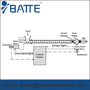
The extruder discharge pressure before the addition of the pump was about 20 MPa, and the process was fairly stable and operated well. The screw channels were previously optimized to a pre-specified rate and a discharge pressure of 20 MPa. After the addition of the pump, the extruder discharge pressure was reduced to about 10 MPa. The line could not be operated at more than 70% of the potential rate due to the excessive oscillation in the inlet pump pressure and consequently the fluctuation in screw speed. The problem was analyzed and found that solids conveying in the first stage of the screw was performing as expected and that the flights were full and pressurized in the first stage of the screw. Since the discharge pressure of the second stage was decreased by half, the length in the second stage that was required to generate the discharge pressure was decreased significantly, moving the position downstream where the second-stage meter becomes first filled with resin. A schematic of the axial pressure profile with and without the pump is shown in Figure 10. For the line without the pump, a typical pressure surge will cause the fill position to start 1 diameter earlier and would cause the discharge pressure to increase to 22 MPa or 10% as indicated by the dotted blue line. When the line was configured with the gear pump, the same surge would increase the extruder discharge pressure to 12 MPa, or an increase of 20% as indicated by the dotted red line. The higher percentage of pressure increase caused the higher pressure oscillations at the inlet to the gear pump and caused the controller to oscillate the screw speed. When the pump was not installed, the pressure fluctuation was about 10%.
Although this level of fluctuation is not acceptable, it did allow the line to produce acceptable sheet.
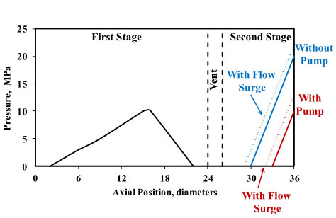
Axial pressure profile for the PS sheet line with and without a gear pump.
The blue dotted line is the expected pressure profile for a high pressure surge without the pump, and the red dotted line is the same surge with the pump.
With the gear pump installed, additional screen packs were added to increase extruder discharge pressure to the original 20 MPa. With these conditions, the screw speed could be increased to full rate with the pressure relatively stable at the inlet to the pump. Long term solutions were found to be an adjustable melt restrictor valve installed directly after the extruder to induce resistance and cause a higher extruder discharge pressure, or the redesign of the second stage of the screw for the expectation of reduced extruder discharge pressure.
Although either solution will work, the preferable course of action is to redesign the second-stage metering section for the reduction in extruder discharge pressure, allowing the processor to take advantage of lower energy and discharge temperature afforded by the pump. For this case, the second-stage metering channel was too deep relative to the depth of the first-stage metering channel. As expected, a similar problem occurs when the second stage is not optimized with the first-stage metering section for processes without gear pumps .
pre:Troubleshooting gear pump assisted single-screw extrusion pr
next:When and why should a melt pump be used?
Inquiry
Please feel free to give your inquiry in the form below. we will reply you quickly!


